
Die Cast Tooling & Trim Dies
Die casting tooling and the trim die that removes flash and runners afterward are designed together, not as an afterthought — a mismatched trim die is a common source of downstream part defects and cost.
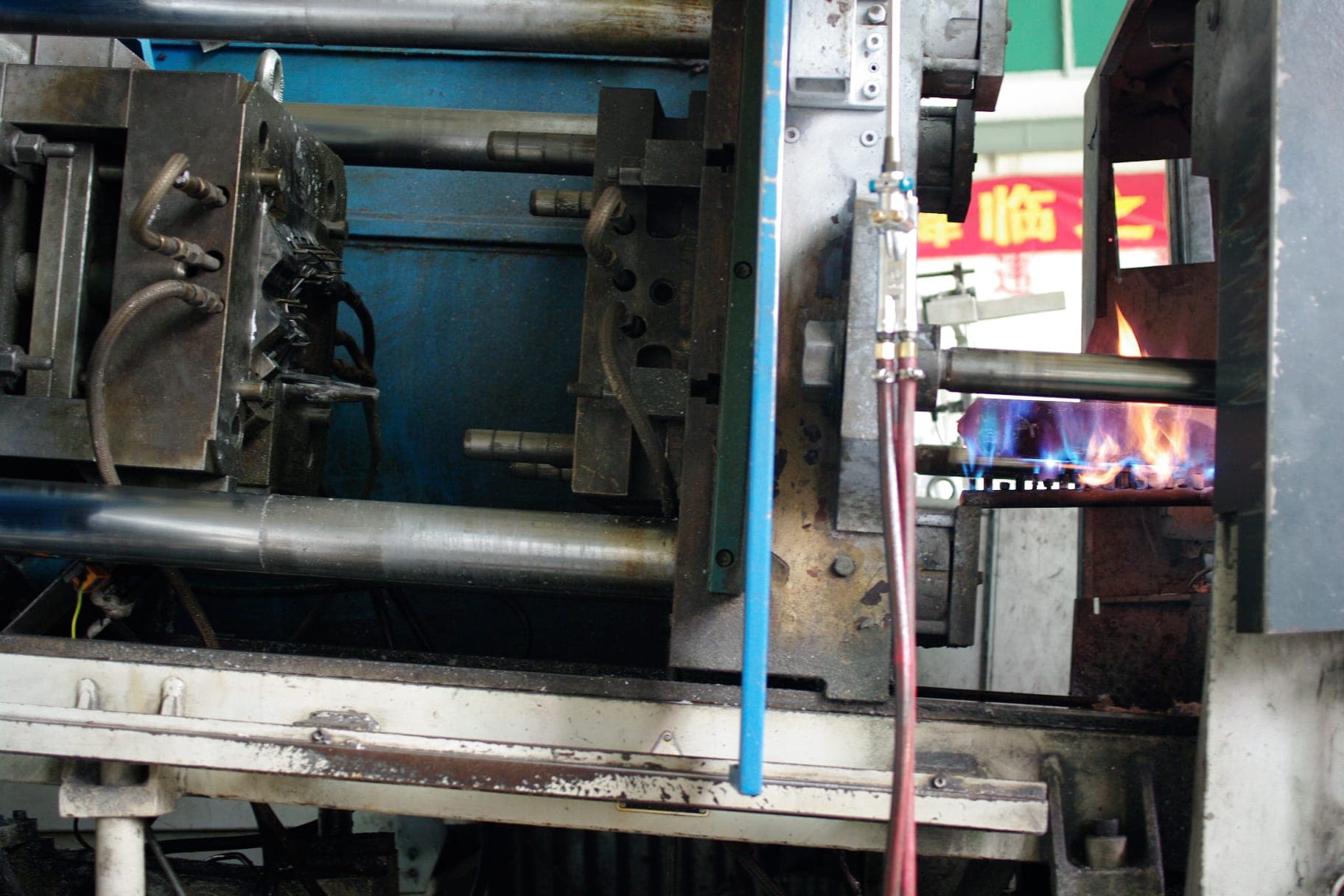
Typical applications
- New die casting tools for aluminum or zinc production
- Trim dies matched to an existing or newly built casting die
- Tool repair and modification for dies already in production
Process overview
- 1
Die design
Cavity layout, gating, and cooling are designed around the part geometry and expected production volume.
- 2
Trim die design
Trim tooling is designed alongside the casting die so flash and runner removal is planned from the start, not reverse-engineered later.
- 3
Build & sampling
Tools are built and sampled, with first-article measurement against the print.
- 4
Production release
Tooling moves to production once first articles are approved.
Part design considerations
- Parting line and gate location relative to trim access and cosmetic surfaces
- Runner and flash geometry that the trim die must remove cleanly
- Tool steel selection matched to expected production volume
DFM guidance
- Confirm production volume early — it drives both die material and cavitation decisions
- Flag any feature requiring tight trim tolerance so the trim die can be designed for it from the outset
Quality controls
- First-article inspection report
- Ongoing tool maintenance and wear tracking for production tooling
Secondary operations available
- EDM and wire EDM for detail tooling work
- Mold/die repair and modification
Frequently asked questions
Can you build a trim die for a casting die we already own?
Yes — send tool prints or the physical die for inspection and we'll design a matched trim die.
What mold life is quoted for an aluminum die cast tool?
80,000 shots is the standard quoted mold life unless the quotation specifically states otherwise. Dies are typically built in hardened H13/8407 or equivalent tool steel. That number counts total cycles — production, setup, trial, and process-development shots, plus rejected castings — not good parts delivered. Normal wear may begin to appear around 60,000 shots depending on part geometry, casting conditions, material, maintenance, and operating parameters; we maintain and repair the die as wear develops to support your quoted production requirement. A substantially higher mold-life requirement generally needs a different and more expensive tooling approach, and is quoted separately.
Ready to talk about your project?
Send your drawings or describe your part — an engineer will follow up, not a sales queue.